Using Human Movement to Control Activities in
Theatrical Environments
Robb E. Lovell and John D. Mitchell
Institute for Studies in the Arts
Arizona State University
Box 872102, Tempe, AZ 85287-2102
Tel: (602) 965-9438
Fax: (602) 965-0961
e-mail:lovell@mythos.fa.asu.edu.
jdm@mythos.fa.asu.edu.
Abstract
Described is a system which allows performers to control theatrical elements of music, lighting, graphics, and video from a stage space. The Virtual Stage Environment provides innovative tools and interesting paradigms for artists to create new forms of performance works. The system functions through the use of video cameras which look at an actor, dancer, or viewer within a structured environment, such as within a stage space or installation setting. By analyzing movement within pre-defined areas, the system responds to what it perceives, and reacts in accordance with user defined responses. These responses correspond to effects which change environmental elements such as lighting, sound, or images. The system is flexible because it allows artists to tailor its aspects: where sensors are located, what kind of actions the sensors are sensitive to, and what responses occur when actions are recognized.
1.0 Introduction
The Virtual Stage Environment is the primary focus of the Institute for Studies in the Art's continuing inquiry into the area of Interactive Media and Human Performance. Computer scientist and dancer Robb Lovell and composer John Mitchell are conducting ongoing research into the possibility of the digitization of human movement in real-time in performance settings, and using this movement to control elements of a stage environment. In the system, a person's movement in front of a video camera interfaces with computational technologies to control a performance environment for artists of many disciplines.
Other areas of study have explored similar objectives. In biomechanics, techniques for image processing exist which allow the motion of parts of the body to be digitized in order to analyze athletic improvements [1]. In computer science, image processing techniques such as stereo and stereoscopic motion analysis are used to crudely determine a distance map of a video scene [2]. Other techniques attempt to digitize three dimensional shapes using multi-view image fusion. In the animation field, some techniques use electro-mechanical sensors which are placed on the body to track the location of limbs in order to move animated figures [3].
Research on movement sensing has been conducted at Arizona State University since the mid-1980's. Beginning in 1991, a program was developed to produce signals based on what was seen by a video camera. This enables the computer to sense movement and the position of a subject in space. This sensing computer is linked to another controller computer which interprets the sensed information by creating theatrical effects such as producing sound, or modifying theatrical lighting.
The system works successfully in a two dimensional framework, allowing dancers to create events by crossing fulstrums which extend out from the camera Figure 1.1. The system is capable of
Figure 1.1 Each trigger is defined within a portion of the image plane of the camera. The region that is sensitive to a dancer in the space is defined by diverging rays which extend out from the camera's focal point.
running on several platforms with varying capabilities. The most current version uses a color digitizer to grab images from three independent cameras, giving the system the ability to create a virtual image that is visible in a three dimensional space. This opens a wider range of creative possibilities for artists.
This research is serving as a stimulus for initiatives in other areas. Dance graduate student Jean Denney is researching Rudolf Laban's theories of Space Harmony, investigating Laban's movement scales by using auditory feedback which describes the location of the dancer's body in space. She is also exploring methodologies for how to use the system in creative processes.
Other possibilities the authors have explored include performer controlled theater lighting, interactive musical compositions, interactive video disk installations, control of real time graphics, control of robotic devices, video game interfaces, and dance preservation.
2.0 History
A. EYES developed at ASU
The original system, first called EYES, was conceived in the mid 70's by Assistant Dance Professor Gram DeFreitus as a music program driven by human movement. The goal was to have a dancer move in front of a video camera and create music. With $2000 from a faculty grant-in-aid program at ASU, Gram DeFreitus and engineer Mark Goldstein created a system which could sense light and dark and send signals to an analog synthesizer [4].
In 1979 work was continued by Dance Professor David Gregory and funded by the Arizona Commission on the Arts over three consecutive years. The system in this form was implemented on an Apple IIe with a Dithesizer digitizing board (resolution 26X27 pixels, 32 levels of gray, 20 fps). The system could then play a set score on the computer's speakers when a person stepped in front of the camera [5].
In the late 80's, Robb Lovell, working under another faculty grant-in-aid award for Dance Professor Rob Kaplan. They recognized the importance of developing the system further and improved the system to recognize presence and motion, and to send MIDI (Musical Instrument Digital Interface) data to external electronic instruments. The concept of being able to insert trigger areas within the video field was also added at this time. In this same period, the program was transferred to an IBM PC compatible platform with a GE 2200 camera and digitizing system (resolution 128x128, 256 levels of gray, 10 fps). In November, 1989 Robb Lovell choreographed a dance piece called ÒAudience MusicÓ in ASU's Forum for New Arts. In the dance, music is created by the sensing system from the movement of the dancer during the performance.
B. Movement Initiated Sound Events, developed at USF
John D. Mitchell began designing ways for dancers to interact with computers while at the University of South Florida. Beginning in 1986 with engineer Richard Miller and choreographer Gary Lund, a system of hardware sensors was used to create a musical dialogue between a dancer and a musician. Hardware sensors, including photo-electrics and pressure-sensitive mats, were converted to MIDI and used to play external keyboards and to access pre-programmed sequences of notes from both samplers and analog synthesizers. This resulted in the performance "Movement Initiated Sound Events" at the University of South Florida in 1988. This performance was featured at the Florida State Dance Festival in the summer of that year [6].
This system was improved and expanded the following year with a New Forms Regional Initiative Grant awarded through the Contemporary Arts Center in New Orleans, LA. The University of South Florida Art Museum sponsored the next performance, called "FLUXION", for the Museum's grand opening in January 1989. In this work, the entire sound score was performed through the movement of the performers in the space. Laser technology and film were also used in the performance [6].
The following year computer animation was added to the control stream, and now performers, including dancers and musicians, were able to control sound and computer animation from the network of hardware sensors. Commissioned by the Center for Arts and Technology at the University of South Florida, "Smarter then Dogs" was a collaboration between artists Bruce Marsh, Roger Palmer, and Robert King, choreographer Gary Lund and composer John D. Mitchell. The work, for percussion, voice, electronic sound, and four dancers, featured large screen projections of computer animation where the performers controlled elements of the computer images and sound [6].
Moving to Arizona State University in 1990, composer John Mitchell, composer Robert Kaplan, choreographer Douglas Nielsen, artist Esther Ratner, and computer scientist Robb Lovell collaborated to create the work "Reversing the Spell". This work, performed in March 1991, marked the first use of MAX, a sophisticated MIDI-based software program that enabled sound, animation, and slide projectors to be controlled with greater accuracy and ease [6].
C. Virtual Stage Environment, Developed at ASU
At this point, through a faculty grant-in-aid award, Robb Lovell and John Mitchell collaborated to improve the system by implementing it on two platforms, separating sensing and event control functions. In that system, all video processing occurs on an Amiga 2500 with a Live! digitizer (resolution 320X200 8 bit color, 20 fps), and all sound and MIDI processing occurs on a Macintosh computer. Event information passes between the Amiga and Macintosh through the use of a MIDI protocol. At this time the system's control functions were greatly expanded to include more complicated sound processing, the ability to control lighting, and video laser disc events. The system has been used in the creation of several performances, including "The Anamorphic Ambassador," "The Last Garden", and various smaller student dance works.
Figure 2.1 The Virtual Stage Environment user interface consists of four windows which display locations of triggers and processing as it happens. The lower right window shows the input video, the lower left is one of the triggers, the upper left is the trigger after thresholding, and upper right is after motion detection. (Dancer Robb Lovell).
The next incarnation of the system transferred the video processing to a Silicon Graphics Crimson workstation with the Video Lab digitizing system (resolution 480x640, 24 bit color, 30 fps). This system adds more powerful capabilities including the ability to place triggers three dimensionally within a space using two cameras; and the triggering capabilities of presence, motion, stillness, and tracking of a single object. The most recent system's interface is shown in Figure 2.1 and exists on a Silicon Graphics Indigo 2 workstation with a Galileo digitizing board and has similar capabilities.
3.0 Survey and Observations
A. Observations
With mainstream culture moving further up and into the world of interactive media, watching video on demand, playing interactive games, and even creating interactive soap operas, how will the creators of live theater and dance performances incorporate these concepts into their new work? Will the audience come to expect, or even demand interactive performances? And how long after that will this altogther cease to be an issue?
At first glance it may seem that the idea of using human movement to control stage media is analogous to the way that computers and robots have been used to automate many manufacturing processes where humans are no longer required to "run the show". It is possible, however that the potential of performer control extends beyond the creation of simple stage mechanization, and could effect the very nature of stage performance and design.
In addition to streamlining technical aspects of stage performance, interactive stage technology presents both new problems and challenges to stage performers and to those who design performances. Besides the usual mechanical problems associated with machine control, interactive stage technology presents creators with the problem of non-linear performance design. It is now possible to create performer centered stage works that can branch in the middle of a performance, with different endings on different nights. Works can be created in modules, to be assembled by either computer randomization or performer choice. And there are many other possibilities, ranging from the small sections or moments of interactivity to whole evenings orchestrated by movement and the computer.
This may require designers to think of their work in non-linear terms. Lighting, scenic elements and costumes might be created to work in various configurations and orders of events. Design elements could perhaps have separate clocks, and function cyclically and independently off one another. Of course, there is an equal if not greater impact on the performer. The performer's attention must shift, or perhaps even split, in order to face the demands of this new responsibility. Depending on the level of control needed, the performer may have to log extensive hours rehearsing with this new computer instrument in order to achieve the designer's desired effect.
B. Survey
Literature on the use of video based interactive systems in the arts is sparse. The following is a sample of some of the interesting work being done that the authors are familiar with.
Starting in the mid seventies Myron Krueger began developing the Videoplace, a system which allows participants to interact with artificial reality animations. Videoplace premiered in 1975 at the Milwaukee Art Museum. The installation consisted of two environments with large screen projections placed 300 feet apart. People in each environment could interact with strangers in the other environment. Since then, Krueger has produced many more animated interactions using Videoplace [7]. Participants in Videoplace face a video-projection screen that displays live images combined with computer graphics. A large sheet of translucent plastic behind the participant is backlit by florescent tubes, producing a high contrast image that enables the computer to distinguish the participant from the background. The system uses a custom frame grabber which can grab at faster than video rates (approximately 60 frames/second).
A commercial system worthy of note is the Mandala Virtual Reality System marketed by the Vivid Group. Developed for the Amiga platform, the system uses a Live! digitizer to grab images of a backlit figure. Participants are able to manipulate graphical objects, play musical notes, and play video games [8].
Another interesting system has been developed by David Rokeby, an independent interactive artist from Toronto, Canada. In Rokeby's system, a Macintosh uses a digitizer to extract two and three dimensional information from a scene and translate this into music. To extract three dimensional information the system uses to cameras with a grid of 256x256 trigger points. An older system of Rokeby's used three Apple IIe's to extract motion information and create musical interactions [9].
Artist George K. Shortess has published work describing some interactive installation pieces which make use of photocells, switches, or infra-red detectors to control elements of the installation [10]. This work is interesting because both sound and video are manipulated.
In the world of Hollywood and graphics animation an explosion of interactive systems are presently under development. Alias Research offers a feature in their animation software which allows users to utilize motion captured data in real-time. The systems are of two types, electro-mechanical and video based. The authors are aware of two video systems: one offered by Cyberware, and the other by Adaptive Optics Associates. Both systems make use of infra-red cameras to extract reflective material attached to the dancer/actor's body [11],[12].
4.0 Description
The Motion Sensing System works through the use of a video camera which views the actor/dancer on stage. A series of hot spots or triggers are setup which corresponds to the stage area and create responses when particular actions occur in that space. A hot spot is created by demarcating areas within a camera's image plane which are sensitive to particular colors or changes in the video Figure 4.1. The computer processes each of these areas several times a second looking for pre-defined actions. Actions are of several types: presence, movement, and stillness. When an action of a particular type is detected, an event is generated which causes a mediated response in the form of music, lighting, graphics, video or robotics manipulations.
The range of manipulations of each media type is varied. In this system, all
Figure 4.1 A trigger is define by specifying a location in the image plane (x,y), a width, and a height (w,h). Values are specified as percentages of the image size because the size of the image can vary.
events (excluding graphical events) are sent to a controller computer which takes the events and interprets them in pre-defined ways. The controller computer manipulates lighting, sound, animations, and video disk players through serial and MIDI connections.
The Motion Sensing System makes use of a visual MIDI programming language called MAX provided by Opcode Systems which allows a user to link together processes which control the flow of data in and out of serial and MIDI ports in synchronous ways. MAX is an visual object-oriented programming language where programs are created graphically by connecting together procedure or object boxes. The connections between boxes communicate messages between procedures. Upon receipt of a message, a procedure executes a method which, in turn, passes messages to other boxes. MAX contains an extensive library of objects which allow the programmer to sense MIDI or serial data, process that data, and generate responses and controlling signals [13]. By using MAX, responses to actions can be programmed corresponding to the creative needs of a performance work.
For example, consider the configuration of the system if a choreographer wishes to have a sound and an image associated with the movement of a dancer in a particular location on the stage. First, a camera is setup to view the stage and a trigger is specified in the video image field which corresponds to when the dancer is in the location desired Figure 4.2. Second, an action is specified in which the
Figure 4.2. An area of a camera's image plane is specified which corresponds to a location on stage. When a dancer crosses this area in the video, an event is activated.
choreographer wishes the system to respond, in this case, a movement action would be sufficient. This action is then associated with a code which will be sent to the controller computers from the sensing computer when the action has occurred. Third, controller computers are informed of the coding of the action through a MAX patch which looks for the coded message. When the patch receives the coded event, it activates some response, such as playing a particular composition or telling a video disk player to display an image. When the code is not present the event is absent: i.e. the music stops or the video disk player is told to display black. This is a very simple example of what the system can be setup to do.
Much more complicated codings and responses are possible. To date, musical interactions are the most diverse and flexible. For instance, an action coding could be the amount of motion on stage or the position of the motion in the video field, and controller responses could be a stochastic or chaotic musical process that are pushed in different directions by the actions interpreted by the sensing computer.
5.0 Implementation
The system exists on several platforms because of the computationally expensive operations that are performed in image acquisition and processing [14]. A Silicon Graphics Indigo 2 handles the image acquisition and processing and a Macintosh Quadra 800 handles the control of actions resulting from trigger events. These two computers are connected via an RS-232 serial link which the Indigo uses to communicate active trigger events.
A. Imaging & Acquisition
The image processing is handled as a continuous loop: grabbing an image, analyzing it for actions, and communicating event information. A Galileo video board inside the Indigo is used to acquire 320x220 color images at 1/30th of a second. Processing of the image is optimized by limiting areas in the image which are analyzed, simplifying operations performed, and by making assumptions about the environment viewed. Processing time varies between 1/30th of a second to 1/5th of a second, depending upon the size of the trigger areas and the operations performed. Communication time is minimal and of little consequence to the processing loop because only small amounts of information need to be communicated, i.e. a person is present or absent from a location on stage. For production type environments the speed of event communication seems more than sufficient. However, for the purpose of accurate and responsive interactions, processing speed is extremely minimal.
Images are represented by the graphics system and digitizer as four bands of information representing red, green, blue, and alpha components of color. Each band is a two dimensional array representing the image plane of the camera, where each cell of the array contains a value between 0 and 255 . Red, green, and blue bands are straight forward and represent red, green, and blue components of the color spectrum The alpha channel is used for transparency by the graphics sub-system and is not used by the Virtual Sensing System.
Because of budget limitations, only one color frame grabber could be acquired, limiting use of color with more than one camera. Through the use of an available RGB encoder, up to three monochrome cameras can be digitized simultaneously. This is done by connecting the composite outputs of each camera to each band input of the RGB encoder, one camera to the red signal, another to the green, and the third to the blue signal. The digitizer board inputs the signal and divides the red, green and blue signals into separate color bands which are easily separated through intersection operations (bitwise anding):
Camera 1 = Red = RGB && 0x000000FF
Camera 2 = Green = RGB && 0x0000FF00
Camera 3 = Blue = RGB && 0x00FF0000
By doing this, each of the three cameras are able to input monochrome signals into the computer in the same time it takes for one color image to be digitized.
The use of two color digitizers would greatly enhance the discriminating power of the sensing system because it allows the system to distinguish hues in three dimensions in addition to intensities.
B. Constraints
What the camera views is as important as how the computer analyzes what it views in an image. The system makes an assumption about the space that is viewed in order to short cut some image processing computations. This assumption is that the figure (the object that creates events in the system) is separated from the background through the use of contrasting backdrops, lighting tricks, or processing tricks. That is to say if a binary or range threshold is applied to an image at some point in the intensity spectrum, the figure will be easily obtained. This assumption limits the capability of the system to actions that produce contrasting effects on the image plane.
Many examples of the kind of actions the system can recognize are evident. For instance, a change of lighting is a contrast changing effect that can be seen by the system. Another example would be a red glove moving across a black background (of course both materials in this case should be matte). In both of these cases, an artist may want the system to respond to these actions. However, a limitation occurs when these actions are part of a performance and not desirable as actions recognized by the system.
If complete control of the performance environment is desired, actions which the system responds to must be choreographed and practiced. Lighting and scene must be established early in the rehearsal process to provide a backdrop for costumes and movements. Once these elements are determined, a set of triggers is designed to match the performance setting and actions desired. If background conditions of lighting or scene change, it will more than likely require modification of the sensing system's thresholds (accomplished through a calibration mechanism).
For many situations, complete control of the environment is not required, instead a more stochastic response is desirable. In this case, the environment still must be established first, although changes evident in the environment will not necessarily produce undesirable results.
C. Capabilities
The system is designed to be able to use a variable number of cameras, either to create individual two dimensional image planes of information, or cooperative three dimensional image cubes. Triggers are defined as two or three dimensional, and assigned to one or more cameras. In the case of a two dimensional trigger, one camera is specified and an area within its image plane is selected for processing. In the case of a three dimensional trigger, two or more cameras are specified to view a common space. An internal representation that relates the geometry of the space in relation to the cameras is used to define the trigger's volume. Each side of the volume is then projected onto each image plane and defines the areas in the image that are processed.
Three types of actions can be defined within the system: presence, movement, and stillness. Three possible values can be associated with each action: the number of pixels associated with the action, an arbitrary pre-defined number, or the location of the action in the image plane or three dimensional space. A presence action occurs when a particular color appears within the trigger area, i.e. a dancer dressed in white against a black background. A movement action only triggers an event if a contrasted element moves against the background. If a dancer remains still while within the trigger space, movement actions do not occur. A stillness action occurs when a contrasting object remains in one place for a pre-defined time.
With each action, four types of events are possible: tracking, signal, magnitude, or configurations changes. With tracking, the position of the action in the trigger or performance space is communicated. A signal event is like a switch which communicates an on or off by sending a number out a serial port. Magnitude events communicate the amount of action occurring within the trigger area. Configurations changes modify the configuration of triggers used by the system.
Each action can be defined to communicate events either continuously, only at state transitions or only during value transitions. Action state changes are detected by means of a threshold mechanism which defines the times when a trigger is active and dormant. There are four states that can be used as points where events can be communicated: active high, active low, the leading edge of a transition, or the trailing edge of a transition.
Thresholds are established as values between 0 and 255 representing a number within the intensity range of the image. Values out of threshold are ignored, and values within threshold are processed. For intensity based processing it is often beneficial to establish a window of values around a particular threshold which corresponds to active actions so that only brightnesses of particular values are valid and cause events. In the sensing system a flexible threshold mechanism is provided. The designer is able to specify that the threshold act as a window where values are valid, or it can be setup to be a cutoff where values above or below the specified threshold are valid. For window thresholds, two values are specified, a base number and an offset. Values within threshold are within the range [base-offset, base+offset]. For cutoff thresholds, two values define the threshold, an intensity and a logical. The logical variable specifies whether values above or below the threshold are within the threshold's range.
Hue sensitivity in a one camera situation is accomplished by providing a set of threshold windows that define which intensity ranges of each color are desired. For instance, if the system needs to be sensitive to only blue within an area, the following set of thresholds constrains the triggers: red: 0-64, green 0-64, and blue 128-255. Colors are calibrated to the right lighting by placing the color in the space under performance lighting and telling the computer to set the threshold to the color of the object plus and minus a threshold window [15].
D. Processing
Processing occurs as a re-configurable pipeline dependent upon the current cameras setup and the user's desired interactions. Each section of the pipe can be modified to perform a different operation based on data obtained from the last section. Initially data is received from one or more cameras and a series of possible pre-processing steps are performed on each image as the first section of pipe. In this step, the images are modified in some way to enhance the features of the action to be detected. For instance in the current system three types of pre-processing steps are possible: averaging, a binary threshold, or an edge operator. The most commonly used operation is the binary threshold which divides all gray levels of one image into two distinct intensities dependent upon a threshold value. The second stage of the pipeline is the processing required to implement an action type such as presence or motion. The third section of the pipe compiles information, codes the action into an event and sends the coded action out the serial port.
1. Actions
For presence type triggers a threshold range defines a particular color or intensity within the image plane. During an operation, the number of pixels in the most current image that are within this range are counted. If the number of pixels counted is greater than the threshold, the trigger is active and a presence action is detected, otherwise it is dormant, Figure 5.1.
Movement triggers are defined similarly to presence triggers with the exception that a derivative calculation occurs before the number of pixels of a particular color are counted. The derivative calculation is simple, consisting of subtracting the most current image from the image immediately previous in time. If the background is dark and the subject is light, a negative value implies that the subject is arriving, a positive value implies the subject is leaving. The magnitude of the value determines the speed of the subject through the trigger space, Figure 5.1.
Figure 5.1. In the set of images above Dominika Borovansky demonstrates the difference between presence and motion triggers. Both images represent a snapshot of the system at a single point in time. In the top image a presence trigger records the dancer's position, whether she is still or in motion. In the bottom image only the dancer's motion is recorded. Notice that to detect motion, two instances in time are needed.
Motion triggers are also able to detect higher order terms of motion, the most important of which is acceleration. Acceleration is detected by comparing two velocities over time. This is accomplished within three time instances by subtracting the velocities of time frames one and two from time frames two and three.
Stillness sensitivity is accomplished by collecting a series of images into a queue. An average of each pixel position is calculated over time and compared with a threshold. A quickly moving object which travels into the trigger area will be recorded within only a few of the images within the queue, and will not contribute much to the average. Conversely, a still object will be recorded within most of the images in the queue and will contribute the most to the average. The longer an object is still, the closer the average will be to the intensity of the object,. Figure 5.2
Figure 5.2 Dominika demonstrates a stillness trigger by standing in one location for 30 seconds and then stepping to her right and assuming a shape. Notice that she is not visible to the sensor when she has moved. Another side effect to the use of stillness triggers is that the motionless image remains for several seconds after the object has moved.
Both three dimensional and two dimensional triggers are handled in much the same way. The processing is the same for three dimensional triggers, except
Figure 5.3 Two cameras viewing the same space intersect to form a box like area representing the common viewing field. Triggers defined in each camera's image plane form smaller intersections further narrowing the field of view. A three dimensional trigger defined in this manner is sensitive only to events within this box like area.
additional image planes are added. For an action to be activated, all image planes viewing the space must detect the action. Only actions within the intersections of the viewing fulstrums defined by the triggers will be detected, Figure 5.3.
For three dimensional triggers it is necessary to calibrate the locations and orientations of the cameras in relation to the viewing space. A two stage calibration technique is used which takes advantage of the radial alignment constraint and projective geometry. Using a series of non coplanar points, Figure 5.4, the program is able to determine the camera's x,y,z focal length, location, pitch, yaw, roll, and radial distortion, [16].
2. Events
Events represent communicated numerical values, messages in response to detected actions by triggers. Four types of events are possible: signals, magnitudes, tracking and configuration changes.
A signal is a switch which communicates an on or off by sending a number out a MIDI or serial port. Each signal trigger is assigned a value which is sent when the action is active.
Magnitude events communicate the amount of action occurring within the trigger area. This translates into counting the number of active pixel within the trigger's sensing area.
With tracking the position of the action in the trigger or performance space is communicated. For two dimensional tracking, two values are sent to the controller computer: the row, and column within the image of the action detected. For three dimensional tracking, three values are sent: the x, y, and z position of the object within the space.
Configuration changes provide a mechanism for modifying trigger sensitivities, positions, and codings. This is accomplished by organizing triggers into groups or patches which can be switched between when a configuration change is triggered.
Signal, magnitude, tracking and configuration events in a two dimensional setting require little processing. Usually,
Figure 5.4 Shown is the calibration device which allows the system to determine how the cameras are oriented. Information is recorded in the relative sizes and shapes of the objects in the camera's image plane.
some sort of normalization or re-scaling is required so that the controller computers know the range of the values communicated. For most triggers MIDI note on and off are used restricting the range of numeric values to 0-127. For larger ranges or for higher resolutions pitchbend coding is used restricting the range to 0-16384. Signals are usually coded as particular numerical values or messages over certain MIDI channels. Since signal events are limited to the communication of off and on type switches, many signal triggers may occupy a single channel. On the other hand, because magnitude and tracking information represent a range of values, triggers are usually restricted to separate MIDI channels. This restriction is limiting because only 16 channels are usually available. More than 16 triggers can be obtained by re-scaling incoming values to different ranges within a single channel's spectrum. For example two magnitude events can be communicated through a noteon event on a single channel by re-scaling one to the range 0-63 and the other to the range 64-127.
Three dimensional tracking events are different from other events because an additional amount of processing is performed. Because tracking locates an object within the space, points within the various image planes must be matched. Once calibration information is obtained matching points in two or more image
Figure 5.5 The block diagram above represents a configuration of the system used for controlling lighting, video, graphics, and audio. Video is digitized and processed by a sensing computer which sends event information to two controller computers. The controller computers use this information to manipulate MIDI and serial controllable devices, in this instance, a MIDI controllable sound board, lighting board, a serial controllable video switcher, and laser disk players. Sound is generated from instruments internal and external to the controller computers. Graphics are generated with real-time interactions from the sensing computer.
planes determines a three dimensional location by calculating the intersection of the rays passing from the focal points of the cameras through the matching image plane points. It should be noted that the cameras should be closer to orthogonal for this approach to work. Another approach which is similar uses closer to parallel cameras and stereo equations to calculate the three dimensional points, however this approach generates larger errors for slightly misplaced image points [2].
Matching points in two or more images is not a trivial problem. In the current system, the computer looks for particular colors or intensities and it is assumed that this color appears only once within the performance space. Thus, the first instance of the color (or intensity level) in one image is by definition a matching point of the first instance of the same color in another image. With this assumption, while limiting, the system is able to extract three dimensional information in real-time (on the order of 15 to 25 frames per second on the Indigo).
E. Controlling
Figure 5.6 shows a block diagram of the system's elements and how they are linked together. Three protocols are used extensively, RS-232, MIDI, and DMX 512. MIDI is a music industry standard for connecting together electronic instruments and consists of both a cable configuration and a communication protocol. RS-232 is an industry standard for connecting devices, and defines only the cable configuration. Protocols sent through RS-232 cables are defined by users in the system through MAX patches. DMX 512 is a lighting industry protocol, similar to MIDI, but with higher communication rates. All graphics, video, and audio links are through normal video or audio cable.
The controller computers are central to the operation of the system. Each controller computer runs Opcode's MAX in order to manipulate sensed data into controller signals. Data is acquired from an RS-232 line using MIDI protocols. This data relates to where the performer is located and how they are moving. Once the designer has decided upon what kind of information a sensing computer needs to acquire, the designers of performance must choose a method of interpreting that information. This is not an easy task because one to one correspondences are often not interesting.
F. Interactions
Interactions are the responses of media to the human performer. Responses vary from one to one correspondences, ramdom interactions, to influencing the parameters of controlling processes. Although different media can be manipulated by the system, the mechanisms for control are similar. for instance a switch trigger can manipulate a video change in the same way that a lighting board cue can be called.
1. Sound
Musical responses have been the most sophisticated interactions dealt with by the authors. The following paragraphs describe a simple example which is then developed into more complex interactions.
The most direct route to achieving a performer initiated stage event is to map a presence trigger on to a single MIDI event,
Figure 5.6 Information comes into this patch from the sensing computer through the midiin object as MIDI notes. The note's velocity or pitch could represent the size of the object within the trigger scaled to a range of 0 to 127. This value is used to play notes on a MIDI instrument
such as a pre-chosen MIDI note. With an array of such sensors a performer can move across the stage activating a palette of pitches chosen by the composer, and can have a large amount of control over these notes with a minimum amount of rehearsal. Figure 5.6 shows a minimum example of a MAX patch which will accomplish mappings of trigger events to pitch responses. In the example, triggers are programmed to send MIDI notes as events in response to actions.
Due to the simplicity and directness of this approach, it affords little possibility for expression or performance nuance. The simple addition of a random event generator will add some interest and unpredictability to the patch, Figure 5.7.
Figure 5.7 An addition of a random note selection creates variability in the responses of the system to a performer.
Presence triggers can also be used to initiate pre-recorded, sampled or pre-ordered sequences of pitches. In Figure 5.8, a counter is used to cycle through a pitch set each time a presence trigger is activated. It begins on C, plays a whole tone scale for two octaves, and ends on C in six seconds.
A more advanced type of interaction utilizes presence triggers to activate changes in the parameters of a generative event. In Figure 5.9, while a whole tone sequence is running and the performer activates the trigger, a drunk (a type of of random event generator) changes the step
Figure 5.8 An addition of a random note selection creates variability in the responses of the system to a performer.
size of the sequence. The performer then interacts with the trigger to obtain desired
step sizes. In similar ways, performers can activate other control elements of a sound generation program including transposition, low frequency modulation or any other parameters accessible to MIDI controllers.
Another method of gathering data from a mover in space utilizes differencing triggers. Areas of the stage may be mapped to separate MIDI channels, allowing specific triggered events to be spatially separated. Continuous MIDI controllers such as extra-precision pitch bend are used to achieve a resolution of 0 to 16384. This data is then processed by thresholding to remove background noise or to focus on a specific range of motion activity, Figure 5.10.
Threshold data can also be split into multiple ranges, and then each individual range mapped to a specific sound or event. In the following example, a base threshold of 500 is set and then the data is split into six unique ranges of 500 values. A sloper patch is used to automatically calculate each individual range, making it possible to easily change several thresholds at once during a performance, Figure 5.11. This is
Figure 5.9 In this example a whole tone sequence is constantly running while the performer has access to the sequence's step size.
particularly useful in working with theater performances where the lighting changes from scene to scene. Thresholds can be set up in advance and then activated by the lighting cues to compensate for changes in illumination.
Once the data is gathered and thresholded, the method in Figure 5.12 can be used to provide meaningful feedback to the performer. In the example, the change in movement from one frame to the next is
Figure 5.10 This example demonstrates how values the sensing computer generates can be filtered out so that certain actions by the performer can be ignored.
Figure 5.11 The sloper patch calculates several threshold ranges at once, where each range starts with the maximum value of the one before it.
scaled and then mapped to pitch, velocity, or tempo. This data is also used to modify physical parameters such as low frequency modulation and sample start point; or can be used to modify sound generation parameters such as set size, instrument choice, or location within a stereo mix. This patch is used to give the performer access to more complex interactions with sound generation. In this example, pitch and velocity information are stored and played back in a random order as long as the performer remains within the motion trigger. This allows the performer to build up complex textures based on their movement history in the space. The performer no longer has direct control over the music and simply influences its direction. The designer is able to set up interesting correspondences between movement and sound gestures.
2. Video
Video responses are achieved through the use of projectors, monitors, video switchers, VCR's, and laser disk players. Here, the choice of what video and the location of where the video is projected can be chosen by the performer. A laser disk allows the system to randomly access video clips to be played and manipulated. The more expensive disk players allow video to be played at varying speeds and backward and forward. This can be utilized by correlating a position on stage with a time point in the video. The clip can then be explored during a performance, played forward, played backward, or frozen.
The location of a video is manipulated through a serial controllable video switcher. In this system an 8 in and 8 out type arrangement is used. The switcher allows the computer to cut between different video sources, sending them to
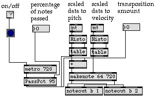
Figure 5.12 This MAX patch, called the improviser, remembers the performers previous actions and feeds those actions back to the performer in complex and varied ways.
different viewing devices. For smoother dissolves between scenes, a MIDI controllable mixer is attached off of two of the switcher's outputs and one of its inputs.
All video devices, VCR's, laser disks, projectors, and switchers must be synchronized to a common black burst source in order to obtain smooth transitions. Unsynchronized sources can be switched to a genlock device through the switcher prior to switching to the target screen if the source is not synchronizable.
3. Graphics
Three types of interactions have been developed in the system which provide real time feed back to the performer and audience. In one interaction a flock of birds represented by colored lines flies according to a flocking algorithm toward the dancer's image in the video. Once arriving at the dancer, the flock lands and assumes the shape of the dancers body in space. As the dancer moves, the flock flies with the dancer. In another interaction the lines represent ropes that bind up the dancer's silhouette. The work of Krueger [7] is very interesting, and he lists many more types of interactions in the area of real-time graphics that are possible.
Another type of graphical response is used for feedback about the body's position in space. Here, a portion of the body is tracked and a trace form is drawn which corresponds to locations traveled through in time. These trace forms are viewed in the act of being drawn and can also be saved and manipulated off-line.
Animations are another type of graphic that a computer can generate in real time. Here an animated figure can respond to motions sensed. For instance an arm gesture or leg gesture can be caused by the position, velocity, and acceleration of someone in a motion trigger.
4. Lighting
Lighting interactions mostly consist of triggers which call lighting cues, but also can involve manipulation of light levels directly. A few of the newer lighting consoles allow the access of dimmer levels directly through MIDI, and many of the older ones allow MIDI access to cues. One interesting interaction that has been used involves the pairing of a motion trigger with light levels, causing light to be correlated with the amount of motion on stage. In this interaction, the light levels change slowly so that the motion trigger remains unaffected. The light levels must remain above a fixed level so that the system continues to see the dancer. Thresholds must be modified in correspondence with light levels as the dancer moves.
5. Robots
The possibility of interacting with a robotic device is very intriguing. At this time only robotic lighting instruments have been incorporated into the system. In one interaction the dancer is able to juggle the light from hand to hand and throw it across the stage through the use of simple switch presence triggers. In another, four teli-operated lights are programmed to move like ocean waves according to a periodic counting process. The dancers are then able to lengthen or shorten the period of each swinging light, simulating the chaotic ordering of crashing ocean waves.
Another robotic interaction that is being explored is the use of moving set pieces including video projections. In the latest experiment a moving video projector is moved along tracks hung from the ceiling and moved with a crane. The projector moves while projecting onto a very long screen. The performer access projector motions through a position trigger and orients the projector with their location in the space.
H. Communication
Events are communicated at particular states of the triggers output signal. Each action can be defined to communicate events either continuously, only at state transitions or only during changes in the triggers output signal. Action state changes are detected by means of a threshold mechanism which defines the times when a trigger is active and times
Figure 5.13. Trigger's communicate information during particular states. Four states are possible: active high, active low, leading edge, and trailing edge. Triggers can limit communication to times when the trigger's value is fluctuating (an on change trigger).
when it is dormant. A change between dormant and active is defined as a state transition. Value transitions are caused by any change in the triggers output value.
There are four states that can be used as points where events can be communicated: on an active high state, active low state, the leading edge of a transition, or the trailing edge of a transition Figure 5.13.
H. Sequencing
In a performance setting it is necessary to be able to switch between different sensing environments. This must be done in response to triggered events and also according to timed sequences. For instance, a sensing environment might need to become active after the first two minutes of a dance, and then disappear after a certain amount of activity occurs within the trigger area.
Changing between environments is accomplished by grouping sensing areas. Each group is associated with an id and a set of attributes related to when the group becomes active and how long it remains active. Figure 5.14 shows an overview of the attributes of a group. Three timing attributes include a wait state before the triggers become active, a timed variable which defines how long the triggers stay active, and a delay phase in which the triggers remain active after they have been told to deactivate. If the timed
Figure 5.14 The attributes of a group of triggers seen in a timing diagram. Groups with a timed attribute of zero remain active indefinitely. Each group starts active or dormant and receives signals from other groups. At the end of activity, the group sends out pre-defined signals to other groups.
attribute is zero, the group remains active until signaled to stop. Groups can start active or dormant and must be signaled in order to change state. A signal consists of a message sent from a particular trigger, or from any group to become active or dormant.
6.0 Use in Performance Settings
A. Issues
Use of an interactive system in a performance setting requires the consideration of certain issues during the creative process: Goal, Form, Control, Interaction, Expertise, Participants. Each issue corresponds to a spectrum of possibilities where the extremes define the possibilities. These issues and their spectrums are discussed by Robert Rowe as they apply to interactive music [13]. Table 6.1 shows an outline similar to Roberts, but expanded to relate to interactive systems in general.
The first issue of goal deals with nature of the experience of the viewer to the system's use. There are three categories that can be defined: performances, compositions, and experiences. Performances include installations, theatrical events, or recitals with some prior rehearsal in the system in order to convey an artistic experience. A compositional system engages the participant in some sort of creative design or activity. Experiential systems are concerned with the viewer's interaction with the system.
The form of an interactive system consists of two shaping qualities: path and order. Path refers to the possibilities of action throughout the piece. Specifically there can be one single thread of action, or multiple threads of thematic material. Order refers to the sequence of presentation of the thematic material, linear, or non-linear. The traditional form is the linear progression where all the material is presented in the same order each performance. In a non-linear presentation, thematic material may be presented in differing orders, not presented, or repeated depending upon the actions during the performance.
Control and interaction go hand in hand. One is the computers attitude toward the performer, the other the performer's attention to the system. On the computer's side is how much it can be controlled, whether it is very sensitive to outside events or only slightly influenced by them. Interaction refers to the responsibility of the performer: whether the performer is required to be attentive or can ignore the system. For more active participation and more sensitive and direct interactions, a high degree of proficiency is required. For indirect and passive interactions no skill is required, and the responsibility is put upon the designer.
The level of expertise required by those using the system is widely varied and may range from novices to experts. Systems which can be used by novices to create interesting effects without prior skill or knowledge. An expert level system requires that a person operate the system with knowledge about how it is set up and what interactions are possible. Often this type of system requires the experience of someone who has practiced with the system extensively.
Finally, the designer must consider how many people will be involved in the interactions. Who are the participants? Should only one person operate the system, or can a group do so? Group interactions are much more difficult than individual interactions because it is more difficult to interpret what is happening in group situations (for example if one person is still and the others moving). It is also necessary to determine if the viewer should be involved as an interactor, and whether they should be aware of their ability to influence the performance.
Table 6.1
Goal: The experience of the viewer, and the process of the creator.
Performance: Implies a presentational setting where prior rehearsal and advanced skill is used.
Composition: This type engages the performer, designer, and viewer in a creative design or activity.
Experience: Concerned with the viewer's interaction in the system.
Form: Shape and construction of the piece.
Path: single-thread, multi-threaded,
Order: linear, non-linear
Control: Attention of the system toward the performer.
Direct: one to one correspondences
Indirect: performer controls flow or direction of computer only.
Interaction: Attention of the performer toward the system.
Active: high degree of precise interaction.
Passive: undirected, peripheral attention.
Expertise: Ability of the interactor to use the system
Novice: A person with no experience can control the media in meaningful ways.
Expert: The system requires practiced use for the success.
Participants:
Who: performer, viewer, or both experience the interaction.
Number: number of people involved in the interaction, individuals to groups.
B. Performances
The Virtual Stage Environment was first used in a performance setting at Arizona State University in a dance called "Audience Music" in the Forum for New Arts. The dance, a solo performed and choreographed by Robb Lovell, is about being absorbed into concentration. The sensing system was used to create a musical score which becomes more frantic and ominous as the dance progresses in a particular location on stage. As the dancer reaches the location, a large screen projection reveals a ghost-like image of the dancer's face and the music begins to play. Once away from this location the music fades out to silence.
The next production "The Anamorphic Ambassador", was funded through The Institute for Studies in the Arts at Arizona State University. The Anamorphic Ambassador was a collaboration between sculptor Dan Collins, choreographer Ann Ludwig, composer John D. Mitchell and computer scientist Robb E. Lovell. The sensing system was used to enable the dancers to "grab" ambassador's voices out of the air in two sections of the dance. Quotations were taken from taped speeches as samples and played when dancer's hands reached into certain areas around a broken down car. In another section, audience members were encouraged to get up and participate in creating a soundscape of ambassador's voices and sampled instruments [6].
In the summer of 1993 a dance/multi-media piece titled "The Last Garden" was created by composer Richard Povall, composer John Mitchell, choreographer Kathleen Smith, and set/lighting designer Jeffery R. Thomson. The work is a fusion of experimental movement, music, video, visual design and technology [17]. The virtual set consisted of three large screen projections, a series of five TV monitors and a quadraphonic sound setup. A camera viewed the stage from an upstage right position. During one section of the piece, the dancers controlled the content of the video displayed on the large screens. Dancers grabbed five of thirteen video interviews during each night's performance through four differencing triggers used as presence sensors. Performances of this section changed from night to night depending upon which video clips were chosen. Differencing information was used to influence musical aspects of the performance. In another section of the piece, a wall of light was used within a presence trigger, becoming a virtual wall. As performer's hands pierced the wall the stage lights flashed, dropped to black and slowly faded up to the original levels. During this section thirteen photo-electric sensors were used in the path of thirteen mini-spots forming a cage around the stage. Photo-electrics sensors provided access to sampled sounds. The performance was also unusual because two composers worked simultaneously on the score. Sonic elements of the score were divided into individual compositional tasks and data from the sensing system was shared to create the score.
C. Future Performances
A future performance, as of the writing of this paper, is under development. Robb Lovell, John Mitchell and choreographer Michael Montanaro will present a collaborative work in Arizona planned for April of 1995. The dance piece involves all of Montanaro's dance company, and is described as a "tapestry of emotions that relate to the travels of people from one place to another" (Montanaro). The piece presents non-linear images of culture, death, and separation and plays with the sense of the passage of time. The work will tap the capacities of the movement sensing technology by controlling intellabeams, producing a sound score, and manipulating video projections, slides and film during the performance.
7.0 Future Work
We are searching for ways to more accurately extract and represent movement. In the future we want to be able to track motions of each part of the body so that gestural information can be incorporated into the system as meaningful events. If this is done, the system will have application in other fields such as animation, virtual reality, and dance notation/preservation. It will also enable the user to create visual compositions from movement, transforming physical reality into three dimensional graphic events.
In order for more accurate three dimensional information to be extracted, the image processing which matches three dimensional points in two image planes must be faster, more accurate, and able to operate in different types of environments. This is a very difficult problem with no general purpose solution in sight. However, we will continue to look at structured environments to enhance the capabilities of the system to match three dimensional points.
The system at this point can only take advantage of two dimensional color processing. In order to process three dimensional color information, the computer needs to be able to digitize from two color cameras simultaneously. When this is achieved, we will look at structured environments which define what the computer looks at through limiting particular objects to particular colors.
Work will continue in developing additional ways in which the system might be used in performance settings. The real difficulty in using the system in live performance settings is maintaining artistic integrity. The easiest way to accomplish this is to camouflage the under-workings of the system. A more difficult problem is to convey meaning through the use of the system. In future productions this will be a continuing theme: using the system in situations where its application provides meaning or direction to a piece, whether in dance, sculpture, theater or music.
Finally, the authors will continue to look for new ways to use the system for interactions. Robotic interactions are particularly interesting because it involves a physical manifestation of the response to the performer's movement.
8.0 Conclusion
The system described uses several video cameras linked into a computer system to control music, video, graphics, lighting, and analog devices. Color images are digitized into a sensing computer and processed to find actions occurring in the video field. Actions detected are of three types: presence, movement, and stillness. Once an action has been detected, an event is communicated to one or more controller computers. Events are of three types: trackings, signals, or magnitudes. The controller computers take the event information and use it to manipulate stage elements.
The system has been used in several performance settings both where the audience was informed of its use, and where they were not. In both situations it was found that the use of the system is not communicated even if the audience is informed of its use. It is always assumed that the traditional model is used where events are controlled from off stage.
However, the use of the Virtual Stage Environment provides a new media through which the artist's hand can create. The system, while not always visible to the audience, allows the performer to more rapidly change and control the environment in responsive, flexible ways that would not otherwise be possible. The system also becomes a creative tool for generating ideas about how to coordinate integrated-medias by providing a means through which to explore possible outcomes in an interactive way.
9.0 Bibliography
[1] Swinkels, J.M.N., Langenbach, D.J.W, "Movement Analysis by Computer for the Explosive Events in Track and Field", Haarlem: Uitgeverij De Vrieseborch, 1985.
[2] Grimson, W. E. L., Marr, D. "A Computer Implementation of a Theory of Human Stereo Vision", Proceedings: Image Understanding Workshop (Palo Alto, CA), pp. 41-47, 1979.
[3] Alias Research, "Film Making Seminar", Hollywood, CA October 1994.
[4] Keary Cannon, "Dance Machine Designed", State Press, Arizona State University, April 29th, 1977.
[5] Gene Luptak, "Teacher Seeks Computer-Dance Link-up", The Arizona Republic, Wednesday, April 20, 1983 SE.
[6] Mitchell, John D., "Interactive Performance Works: the Computer at the Center of MIDI-Based Performance Systems", Moving Toward the Future, the First International Conference on Dance and Technology, pp. 41-45 1992.
[7] Krueger, Myron W., "Artificial Reality II", Addison-Wesley Publishing Company, 1991.
[8] The Vivid Group, "The Mandala Virtual Reality technology", Press Release, 1990.
[9] Public Broadcasting at USF, "Interview with Richard Loveless: video clip of David Rokeby's system", Art Stage; Information obtained in phone conversation with Rokeby.
[10] Shortless, George K., Interactive Sound Installations Using Microcomputers", Leonardo, Vol. 20, pp. 149-153, 1987.
[11] Cyberware, "Video Presentation", Press Release, 1994.
[12] Adaptive Optics Associates, "Capture Motion, Release Creativity With Multi-Trax 2D and 3D Unencumbered Trackers", Press Release, AOA Inc, 1994.
[13] Rowe, Robert, "Interactive Music Systems, Machine Listening and Composing", The MIT Press, Cambridge, MA, 1994.
[14] Agha, Gul, "Actors, A Model of Concurrent Computation in Distributed Systems", The MIT Press, Cambridge, MA, 1990.
[15] Gershon, Ron, "Aspects of Perception and Computation in Color Vision", Computer Vision, Graphics, and Image Processing, Vol. 32, pp. 244-277, 1985
[16] Tsai, Roger Y., "A Versatile Camera Calibration Technique for High-Accuracy 3D Machine Vision Metrology Using Off-the-Shelf TV Cameras and Lenses", IEEE Journal of Robotics and Automation, Vol. RA-3, No. 4, August 1987.
[17] Povall, Richard M., "The Last Garden: Explorations in Interactive Performance Methods", Leonardo Music Journal, Vol. 3, pp. 25-28, 1993.
 Robb E. Lovell is a computer scientist and is currently doing research into uses of technology in the arts at the Institute for Studies in the Arts. He has an Master of Science in Computer Science from Arizona State University and is an accomplished systems engineer. His main interests lie in the areas of computer applications in the arts, image processing, autonomous navigation, and computer graphics. Mr. Lovell returned to the Tempe Arizona last year after working at Goddard Space Flight Center where he design an object-oriented database for storage and retrieval of satellite-observation metadata and performed research in automatic geo-registration, categorization, and co-registration of satellite images. He is currently implementing a "virtual stage environment" which allows performers to cause or create musical, lighting, video, or graphical interactions. He is also creating artificial life worlds which are used to modify visuals and sounds as an emergent sculptural installation. Mr. Lovell is an accomplished dancer/choreographer and has performed with Dance Arizona Repertory Theater and as guest artist with Desert Dance Theater and a ludwig co.
John D. Mitchell is a composer and performer, concentrating on creating performance works with artists from diverse disciplines. These works focus on using computers as interactive tools to expand the sensory and creative experiences in the performing arts. He has worked extensively to create dynamic movement-sensing environments that enable performers and viewers to interact with a variety of media including computer generated sound, computer animations, slides, video laser-disc and tele-controlled lighting. Currently a a Resident Artist Fellow with the Institute for Studies in the Arts, Mr. Mitchell is also developing new computer-based teaching tools for the Department of Dance, both at Arizona State University.